公司简介
Arkwright Technologies Pty Ltd was incorporated in May 2015 by Professor John Arkwright. Shortly after incorporation, the Company was granted full rights by the CSIRO to commercialise innovative Fibre Optic Manometry (FOM) Catheter technology developed by Professor Arkwright and colleagues during his time working for the CSIRO.
技术能力
Arkwright Technologies devices are based on two basic transducer designs.
The original device consists of a single fibre containing a fibre Bragg grating (FBG) formed during the fibre draw (DTG™, FBGS International, Jena, Germany). The fibre is bonded into a rigid substrate with a preloaded curve to increase its sensitivity. This design has allowed us to achieve pressure sensitivities of better than 0.01 mmHg (1.3 Pa, 0.14 mmH2O, 0.13 mbar, 0.00019 psi). This basic sensing element is temperature sensitive and so is used in isothermal environments (such as the human body) or for dynamic applications in which change in value are more important than absolute values (such as acoustics).
Our second patented transducer design overcomes the inherent temperature sensitivity of fibre Bragg gratings by using a pair of DTG gratings wound together in a helical configuration. In this design, the two FBGs are oriented one on top of the other at the point where the helix is vertically aligned. Applying a force or pressure on the upper fibre distorts the helix downwards, reducing the strain in the upper fibre and increasing it in the lower fibre. The applied force is then proportional to the change in reflected wavelength experienced by the FBGs in the upper and lower fibres. Since the applied signal is proportional to the differential change in wavelength of the two FBGs, whereas any change in temperature acts equally on both FBGs, the signal is independent of temperature. Figure 1 shows an image of the helically wound transducer and Figure 2 shows the response of the transducer to changes in applied force as the ambient temperature is increased from 21 °C to ~60 °C.
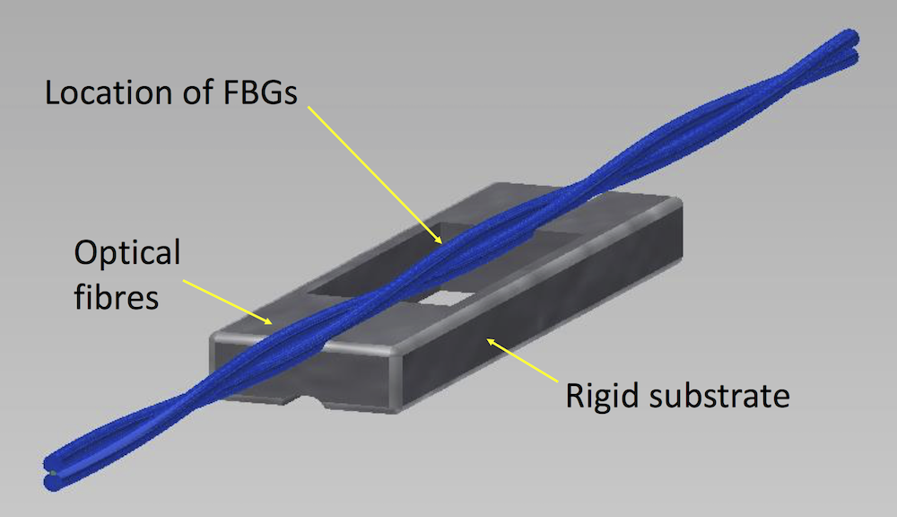
Figure 1: A schematic of the patented temperature compensated FBG transducer.
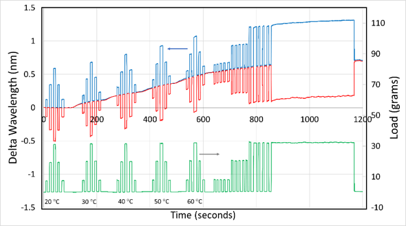
Figure 2: Response of the patented AT transducer to a series of calibrated weights applied to the upper fibre, showing the change in wavelength of the upper and lower FBGs (red and blue curves respectively) as each weight is applied, and the calibrated load calculated from the differential change in wavelength of the upper and lower FBGs. The ambient temperature of the sensor was increased in steps from 21 °C to 60 °C during the data acquisition.